Honeywell Decorative Wall Lantern Manual
11"
Fold
Fold
Fold
17" Fold
Fold
17" Fold
EN | 2 EN | 3 EN | 4 EN | 5
APP HELP
If you are unable to reset your user name and password using the app on your cell phone, follow these steps.
A) During daytime cover the light sensor with a black cloth or tape which will turn on the lantern. Remove
the cloth or tape and the lantern will turn off. Repeat this 5 times within 20 seconds until the light flashes red.
Proceed to step C.
B) During night time shine a bright light near the light sensor to turn off the lantern. Remove the bright
light and lantern will turn on. Repeat this 5 times within 20 seconds until the light flashes red.
Proceed to step C.
C) Enter default password "1234" to control light.
NOTE: To create new password, tap the lock icon on the app screen. Select desired password option and
reset the password using your own number sequence. Note that any previously saved functions will need
to be reset. Online password recovery is not currently supported.
RESET BUTTON INSTRUCTIONS
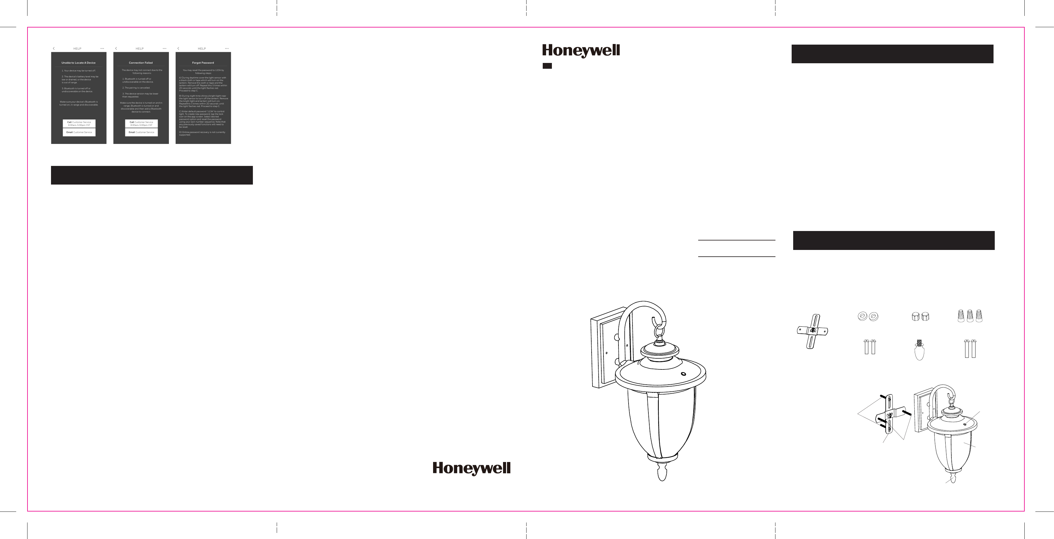
INSTALLATION
CAUTION: Before beginning installation turn off the circuit breaker and light switch.
STEP 1
Tighten finial (Part F) to bottom of lantern by turning clockwise until secure. (Figure 1)
STEP 3
A. Place wall lantern (Part I) over pre-installed screws on the mounting bracket (Part A)
and through the mounting holes located on both sides of the wall lantern mounting base.
(Figure 3)
B. While holding the wall lantern (Part I) over mounting bracket (Part A) with the installed
screws (Part G), make sure the the both screws (Part G) protruding through mounting holes
of the wall lantern mounting base.
C. Secure to the mounting bracket (Part A) using washers (Part B) and screw caps (Part C) onto
the protruding screws in the previous step.
A
E
D
STEP 2
RECOMMENDED: Wrap each wire nut with electrical tape (not included) after wires have
been attached.
First installed screws (Part G) on the mounting bracket (Part A). Position the mounting
bracket (Part A) to the junction box and secure using screws (Part E). Connect the AC
wires to the corresponding wires (BLACK to BLACK, WHITE to WHITE and GROUND to
GROUND) in the junction box using the wire nuts (Part D). (Figure 2)
WARNING: Changes or modifications to this unit not expressly approved by the party responsible for
compliance could void the user authority to operate the equipment.
**********************************************************************************************
NOTES:This equipment has been tested and found to comply with the limits for a Class B digital device,
pursuant to Part 15 of the FCC Rules. These limits are designed to provide reasonable protection against
harmful interference in a residential installation. This equipment generates, uses and can radiate radio
frequency energy and, if not installed and used in accordance with the instructions, may cause harmful
interference to radio communications.
However, there is no guarantee that interference will not occur in a particular installation. If this equipment
does cause harmful interference to radio or television reception, which can be determined by turning the
equipment off and on, the user is encouraged to try to correct the interference by one or more of the
following measures:
• Reorient or relocate the receiving antenna.
• Increase the separation between the equipment and receiver.
• Connect the equipment into an outlet on a circuit different from that to which the receiver is connected.
• Consult the dealer or an experienced radio/TV technician for help.
FCC WARNING:
TROUBLE SHOOTING
PROBLEM
Light will not come on. A. Fuse is blown or circuit breaker
is turned off.
B. Incorrect circuit wiring.
A. Replace fuse or turn circuit
breaker on.
B. Verify that fixture is wired properly.
POSSIBLE CAUSE SOLUTION
Lights come on during
the day.
A. Photocell covered. A. Clean photocell with damp cloth.
PHOTOCELL
INSTALLATION
STEP 4
Caulk completely around the area where the canopy meets the wall surface with silicone caulking
compound to prevent water from seeping into the junction box. Turn power ON at the circuit
breaker. Verify light function. (Figure 4)
NOTE: Verify light function by covering photocell with piece of electrical tape. Light should
come on. Remove electrical tape. The silicone is not included.
WALL LANTERN MOUNTING BASE
G
G
BA
C
SILICONE CAULKING (Not Included)
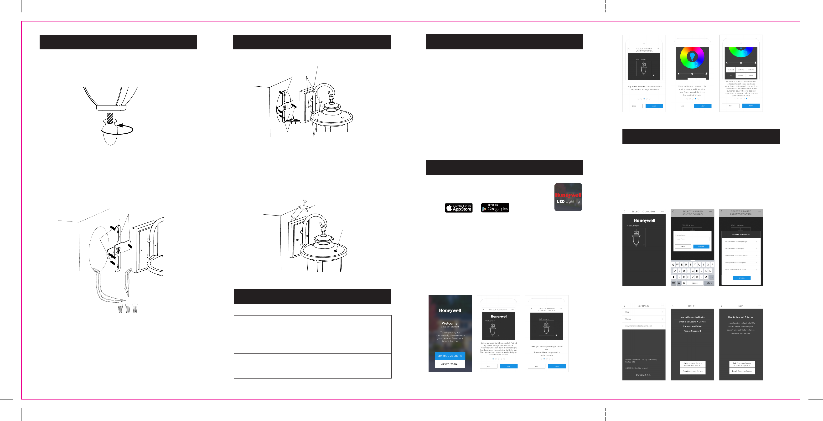
BLUETOOTH OPERATION
STEP 1: Download the Honeywell LED Lighting App for free from Apple or
Google store depending on your device.
Note: That App compatibility is only with iPhone (4S generation and iOS 7.0
or above) and Android devices (5.0 or above).
STEP 2: Make sure your mobile device's Bluetooth is enabled.
STEP 3: Open Honeywell LED Lighting App on your mobile device and
select View Tutorial for instructions or select Control My Lights to begin using
your lights.
STEP 4: Select and tap a paired light from the list. Paired lights will be highlighted in white with a
number in the lower right hand corner. The number indicates the available lights which can be paired.
Enter the default password 1234 (when prompted). From this point, you can either tap the light icon
to turn fixture on or off or press and hold the light icon to open the menu to control the light.
A) Color wheel - select specific color using wheel.
B) Preset and custom colors - select preset mode to display colors in various preset sequences or
customize up to 3 colors. Press and hold custom button to save the customized color.
C) White - Default your light to white only tone.You can select desired brightness by moving bar from
lighter to darker.
APP TUTORIAL
F
(Figure 1)
(Figure 2)
(Figure 3)
(Figure 4)
Sky Rich Star Limited
UNIT E, 10/F, WORLDWIDE CENTRE,
123 TUNG CHAU STREET, TAI KOK TSUI,
KL, HONG KONG
Toll-free: 1-877-723-0723
Made in China
© 2018 Sky Rich Star Limited, all rights reserved.
The Honeywell Trademark is used under license
from Honeywell International Inc.
Honeywell International Inc. makes no
representations or warranties with respect
to this product. This product is manufactured for
Sky Rich Star Limited.
LED Outdoor Wireless Color
Changing Wall Lantern
Use and Care Guide
Read and Save this Instructions Before Use
EN
Model: BT0312AA0820
11"
Fold
Fold
Fold
17" Fold
Fold
17" Fold
EN | 6 EN | 1
A:
Mounting Bracket (1)
C:
Screw Caps (2)
8.7 mm x 7 mm x 8.5 mm
B:
Washers (2)
10 mm x 4 mm x 2 mm
F:
Finial (1)
D:
Wire Nut (3)
P3 12 mm x 21.5 mm
E:
Phillips Head Screws (2)
8-32UNC x 20
G:
Phillips Head Screws (2)
M4 x 32mm
SAFETY INFORMATION
PRE-INSTALLATION
WARNING: Read all safety precautions and installation instructions carefully before installing or
servicing this fixture. Failure to comply with these instructions could result in a potentially fatal
electric shock, fire, and/or property damage.
• To reduce the risk of electrical shock or other personal injury, ensure the power is turned
OFF at the fuse or breaker box before making any electrical connections.
• For outdoor use only.
• Must be connected to 120 volt, 60 Hz power source.
• Fixture should be mounted to a grounded junction box marked for use in wet locations.
• Suitable for wall mount.
• NOT suitable for ground locations. Minimum of 4 feet or higher.
• Wall lantern should be installed by a qualified electrician or person experienced with
household wiring. The electrical system, and method of electrical connection of the fixture,
must be in accordance with the National Electrical Code and local building codes.
SUITABLE FOR WET LOCATIONS
CONSULT A QUALIFIED ELECTRICIAN TO ENSURE CORRECT BRANCH CIRCUIT CONDUCTOR.
MINIMUM 90° C SUPPLY CONDUCTORS
THIS PRODUCT MUST BE INSTALLED IN ACCORDANCE WITH THE APPLICABLE INSTALLATION CODE
BY A PERSON FAMILIAR WITH THE CONSTRUCTION AND OPERATION OF THE PRODUCT AND THE
HAZARDS INVOLVED.
PLANNING INSTALLATION
• Turn off the electrical power at the fuse or circuit breaker box before installing or servicing
any part of this fixture.
• Carefully remove the fixture from the carton and check that all parts are included. Be careful
not to misplace any of the screws or parts needed for installing the fixture.
HARDWARE INCLUDED
PARTS
I - Lantern
A G
EH
I
F
H - Light Sensor
A - Bracket
F - Finial
Trademark Attribution Footnote
Whenever the Bluetooth Trademarks are used in a particular piece , they must be attributed with an
appropriate trademark footnote. The recommended attribution footnote is as follows:
"The Bluetooth word mark and logos are registered trademarks owned by Bluetooth SIG, Inc.
And any use of such marks by SKY RICH STAR LIMITED is under license. Other trademarks and
trade names are those of their respective owners."
®
Honeywell Decorative Wall Lantern Manual
Source: https://usermanual.wiki/SKY-RICH-STAR/BT0312AA0820/html